Howto:Door opener with analog FXS port
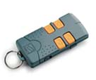
Many customer have electric driven gates, garage and entry doors or similar. They usually can be opened with a button from inside or with a remote control.
Those remote controls have two unappealing properties: you forget them always and they are annoying to carry, also because each door has his individual, non compatible system; two different doors requires to two remote controls. So giving an employee a remote control is expensive and like giving him a key: if he loose the remote control…bye bye security, change the system in the worst case.
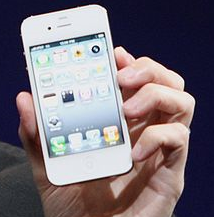
On the other hand in our days we all use the cellular phone for nearly everything: work, private, communication, internet, gaming (not in innovaphone of course) etc. So why not use the GSM-Phone as a door opener instead using a remote control?
With an innovaphone PBX this feature is at your fingertip!
Add many remote controls as you like (for example each employee can have one) and manage the “distribution” of the door opener in the PBX. A new employee is no task, just insert his mobile phone number in the PBX; if you won’t anymore that a certain number should be able to open just cancel the number. Of course you can open the door not just from cell-phones but each user in the innovaphone PBX can open the door using the IP-phone; for example pressing a function key on the phone of the reception. So to open the door you just have to call a number, the door will open and you hear a “beep” (of course if you like, it is also possible to play any message or extend the functionality and ask also for an additional PIN o similar).
In using cell phones maybe you want open the door without any answer or confirmation. Doing so there are no call costs because nobody is answering the call but the door opens. Please note that in this case you will need a DID trunk line to reach the door opener number.
How is this possible and what are the requirements? It is simpler then you imagine. Here is how.
Applies To
This information applies to
innovaphone PBX: V8 or higher on every platform
Analog ports on IP302/IP22/IP24/IP28
Note: For all devices HW 402 or higher. Older HW platform could eventual not work, check it first.
More Information
The feature is a combination of a XML and easily available cheap electrical hardware components. You will need also a free analog port of an analog interface (IP22/IP24/IP28 or analog port on an IP302). The feature requires one port license because the analog port must have a number in the PBX. To open the door a user calls a XML, means a VM-Object in the PBX. The XML then calls the analogue port and make just one ring and then drop the connection. How to limit calls to a certain number in an innovaphone PBX is not described in this article (using filter, routes, WQ and similar) but simple and well known. Also inserting PIN codes in WQ or number maps for enhanced security is not described but well known. If there is no DID line to reach the XML from outside it is also possible to reach the XML using a WQ and dial with DTMF codes. In this case if course the WQ answer the call and charge is applied.
Electrical installation
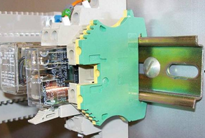
Electrical doors needs a single closed contact impulse to open (or close) a door. Exact what happens if you press a button once. Or the remote control key (in that case a relay in the receiver will close for one second and give so the opening or closing impulse). So the technical task is to close an electrical contact, but just one time. Electrical driven doors or gates are always controlled from a cabinet housing the receiver, the power transformer and similar. So we have to bring our analogue extension line in this case. Those cabinets typically are equipped with a 35mm DIN rail (known also as top-hat rail) widely used for mounting circuit barkers and industrial control equipment:
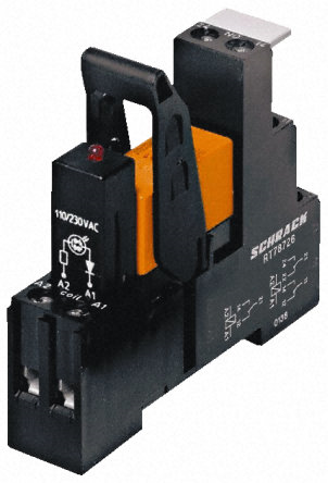
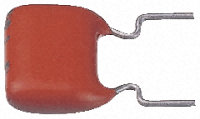
For the door opener we need a DIN mountable, 24Vac relay with at least on free contact and a condenser 4,7µF 100Vac. One possible relay with 2 floating changing contacts available worldwide you can find here: http://www.rs-components.com/index.html Search the product number 494-0536.
The next picture shows the product, the producer is Tyco Electronics, Part number RT3S4R24 and the list price for one piece is about € 7, the total cost for those 2 components will be less than 10€.
In doing this shopping you can buy also a condenser, a possible product is part number RS –components 115-629, producer Vishay part number BFC236825475.
Please do not use electrolytic capacitors, remember that „ringing“ is always a alternate current!
Now let’s look how to connect them.
But before beginning to install remember: be carefully operating in cabinets where eventually even 220Volts components are!
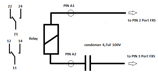
Here the not very complicated electrical diagram:
Practically you connect the relay screw contact A2 to one leg of the condenser and the line to the analog port to the other one, the second wire to the A1 contact. The analog ports use just the two central lines, so pin 2 and 3 of the RJ11 plug. Doing this the “PBX” side is ready; now collect PIN 11 and 14 (or 21 and 24) parallel to the door opener key (or output of the remote controller). As you see from the diagram this contacts of the relay are floating and can switch up to 8A and 250 Volts (2000VA), but typically there are just some Volts and mA to switch. For further technical details see relative data sheets of the relay (available also in the rs-components web). Please note that the relay shown has a led indicator that consumes a lot of power. Fortunately the led is located in a small module that can be plugged out. There is no difference in operation; you just will not see the led. We recommend to remove the led module, in this case even a 2µF condenser is large enough to provide power for the relay.
Installation
To install the XML first unzip the Download ZIP file. Now edit with a text editor the file “DoorNumber.txt” and put in the PBX Number for this service. Please note that this file has yet the number “88” in to show you the format. Now create a directory on the CF and copy all the files in.
Configuration
As you see there are two XML in the zip file, one answers the call and play a “beep” (indoor.xml), the second one plays nothing and will not answer the call (indoorNR.xml). You have to known that a call without response remains active until the caller gives up. A call answered instead will be active dropped after the beep. We recommend to use the non response version (indoorNR.xml) just for external calls if DID available. In all other cases use the answer call version (indoor.xml). We recommend use both of them, for external DID calls the indoorNR.xml and for all other calls the indoor.xml. Configure a VM-Object (or two if you use both XML) in the PBX, the VM object will not require any license. Point the url on the compact flash and on the XML (“indoor.xml” or “indoorNR.xml”). Your url will be similar to following one (created a directory “IDO” in the CF): http://xx.yy.yy.ww/DRIVE/CF0/IDO/innDoor.xml Now do the setup of the analog port. We recommend doing the following setup in the physical interface: Ringing voltage low, ring Threshold: high Important: select “Internal/External call distinction” to “always external”.
The rest is basic PBX configuration. Read relative articles how to limit calls for specific user to a destination (filter, routing). Do not call the analogue port directly but force all calls to the XML. Please note that for external caller is must be possible to access to the XML. No problem if you have a DID, but if not it will be necessary to activate a WQ with the possibility to reach with DTMF the VM object. Last item: add in the address book of your GSM Phone the “Open Company Door” Number.
External Ringer
If you call the analogue port directly the relay will close and open at each “ring”. That could be used for an additional feature, for example if you have the problem to switch horns, High power-bells or lights if a call came’s in: do parallel ringing with the phone and the job is done. No XML is needed of course for that feature.
Known Problems
The remote control will work just in the near of the Door to open, but the GSM Phone can open the door from everywhere. That could be an advantage, but it is also a risk: imagine for example that you call the door open number erroneously. If you are afraid about that you can add additional DTMF codes for opening in a WQ for example. On the other hand in most cases if the company is “real” closed a mechanical key lock is done and you have in any case use a mechanical key to access (and not just the remote control).
